


SPArKy_Dave
-
Content Count
10,781 -
Joined
-
Last visited
-
Days Won
189


-
-
-
Some archived info from around the net, on fitting a BA-BF wiper motor to XD-XH Falcons Ford Falcon XD XE XF Hi all, Looking to improve the windscreen wiper performance on an XD. Has anyone been able to improve it Re-firb or re-fit Facebook.pdf
-

BF Fairmont tail and dash lights not functional
SPArKy_Dave replied to XF EDDIE's topic in Auto Electrics
Do the front parkers work? I'd suss the binnacle switch, and/or relay Remove the relay and jump the load side relay contacts, using low amp test light (in case of wiring short) -
82DA, sounds like the diff has been swapped maybe? Suss out the drum brake wheel cylinders If they're original PBR or Girlock, they have date codes on them
-
XG front discs have larger bearings I believe, plus the larger diameter hub, same as XG rear The XB spindles may be smaller diameter too, I believe? 10's fit on the coupes, but I don't think they fit on any others without quarter panel modification
-
New, reproduction speedo sender gears are available I believe? I know the brown 20tooth gear, suits 3.27 diff, with 15inch wheels 205/65/15 tyres, or 16 inch wheels with 225/50/16 tyres
-
A 78DA-7003-AB gearbox, is from an 81' onwards XD They were used in either 3.3/4.1 or 4.9 XD's, possibly very early XE's. Shorter ratio gearbox, I believe
-
Looking at the Exedy website, all the single rails (even 3speed) are 10 spline on the clutch friction plate 3speeds just have a smaller diameter shaft at 24mm, over 27.5mm The info regarding 19/20/21/22 splines, relates to the opposite end of the input shaft, internal to the gearbox? First screenshot is all XD, and XE up to 05/82 Second screenshot is XE only, from 05/82
-
The following is a list of settings that can be altered, to suit personal preference - Personalisation Settings: Taxi Mode: Disabled: Means car is in normal mode. Door locks operate in a standard manner either 2 stage unlock or 1 stage unlock. Enabled: Car is in taxi mode. Remote key operates in a normal manner,but operation of central door lock(CDL) switch on the ICC is different. If any door is unlocked when the ICC CDL button is pressed the passenger doors will unlock (drivers door will remain locked) Panic Alarm Inhibit: Disabled: Allows operation of hazards,horn warning and courtesy lamps as a result of pressing of panic alarm button on remote key pad. Enabled: Disables operation of panic alarm. If this bit is set and panic alarm button is pressed on remote key pad nothing will happen. Door Trigger Disable Mode: Disabled: Means dome lamp operation will be triggered by opening and closing of doors. Enabled: Opening and closing the doors will not effect state of dome lamps ie.Opening a door will not turn on dome lamps, and closing a door will not turn off dome lamps. Also key out/dome on function will not operate. There is still control of dome lamps by operation of the ICC button, and operation of remote key. This bit can be set and reset by either using the WDS or alternatively pressing and holding the dome lamp button on for 5 seconds. Master Door Trigger Disable Mode: Disabled: Allows door trigger disable mode to be invoked by pressing and holding of ICC CDL switch. Enabled: Does not allow door trigger disable mode to be turned on or off by pressing and holding ICC CDL switch. Hazard Warning Inhibit: Disabled: BEM will operate the hazard lamps when any remote key is pressed and for key in lock warning. Ie unlock,panic,lock,remote boot release. Enabled: BEM will not operate the hazard lamps if any of the remote key buttons are pressed. Horn Warning Inhibit: Disabled: BEM will operate the horn in the event that the remote lock button is pressed twice within 3 seconds, or if the remote lock button is pressed when a transponder is still in the ignition. Enabled: BEM will not operate the horn under conditions described above. Battery Saver Inhibit: Disabled: Enables battery saver supply to operate as per normal operation. Enabled: Disables battery saver control by BEM when ignition is off. Remote key operation will not activate courtesy lamps. Door opening and closing will not activate dome lamps with ignition off bacause battery saver is not active when ignition is off. Battery saver will still be active when ignition is in the Accessories or Ignition on positions. Courtesy Lamp Inhibit: Disabled: Enables courtesy lamp output driver, such that courtesy lamps operate as per normal operation. Enabled: Disables courtesy lamp output driver. Courtesy lamps will never operate.
-
Did you unbolt the steering column, to remove the cluster? To me, it's all voltage and/or earth related Focus on the ignition switch Does it have an aftermarket alarm/immobiliser?
-
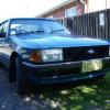
From memory, that's been for sale for a few yrs now Earlier factory NON aircon XF's, didn't get the deflectors, or that rubber strip plus smaller radiator, and top metal fan shroud I think later on, all XF's got the side deflector plastics and bigger radiator, but still no rubber strip. (aka, my 92' XF ute for ref, which has aftermarket aircon) I see replacement door rubber seals fitted, non original spark plug leads, bonnet strut fitted upside down, wrong battery cables, along with painted over windscreen wiper bolt heads, and painted over spring clamps for the windscreen washer jet hose.
-
Is it maybe a really high rpm stall converter? Lack of 3rd, could be a sticking actuator in the valve body, or a sticking governor in the extension housing. Can you monitor line pressures, whilst driving it?
-
I'd check for bent conrods, using a straw, plastic stick or similar, down the spark plug holes.
-
-
SUGGESTIONS WELCOME for an EA to FG forum sections, tips and how to's
SPArKy_Dave replied to deankxf's topic in AU HEY YOU Q&A and general info series 1,2 and 3
Shims usually live behind the upper arm front mount I thought, used to increase caster, by pushing the top pivot point back? The upper arm clamp, should self center on the ball joint recess, when fully tightened? And yeah, lower ball joint wear caused excess toe/camber on my BF. It had been previously aligned to compensate, but when I fitted new ball joints, I didn't think to re-adjust. Note - After not adjusting the alignment, it wore the front tyres, within around 15,000km's. When later fitting new tyres, I located whiteout marks for the factory toe settings, and set to those points. Further confirmed, with a DIY string/tape measure arrangement. -
Anyone got a photo of the xf ute spare tyre retainer?
SPArKy_Dave replied to XF EDDIE's topic in Body and Exterior
That's it yes! The loose threaded bracket, sits against the tyre, with the threaded end in the slotted hole of that welded bracket. The wingnut winds on the thread upside down, so it tightens backwards against the outside of that welded bracket, thus pushing the loose threaded bracket, against the tyre.
