


damo9999
-
Content Count
21 -
Joined
-
Last visited
Posts posted by damo9999
-
-
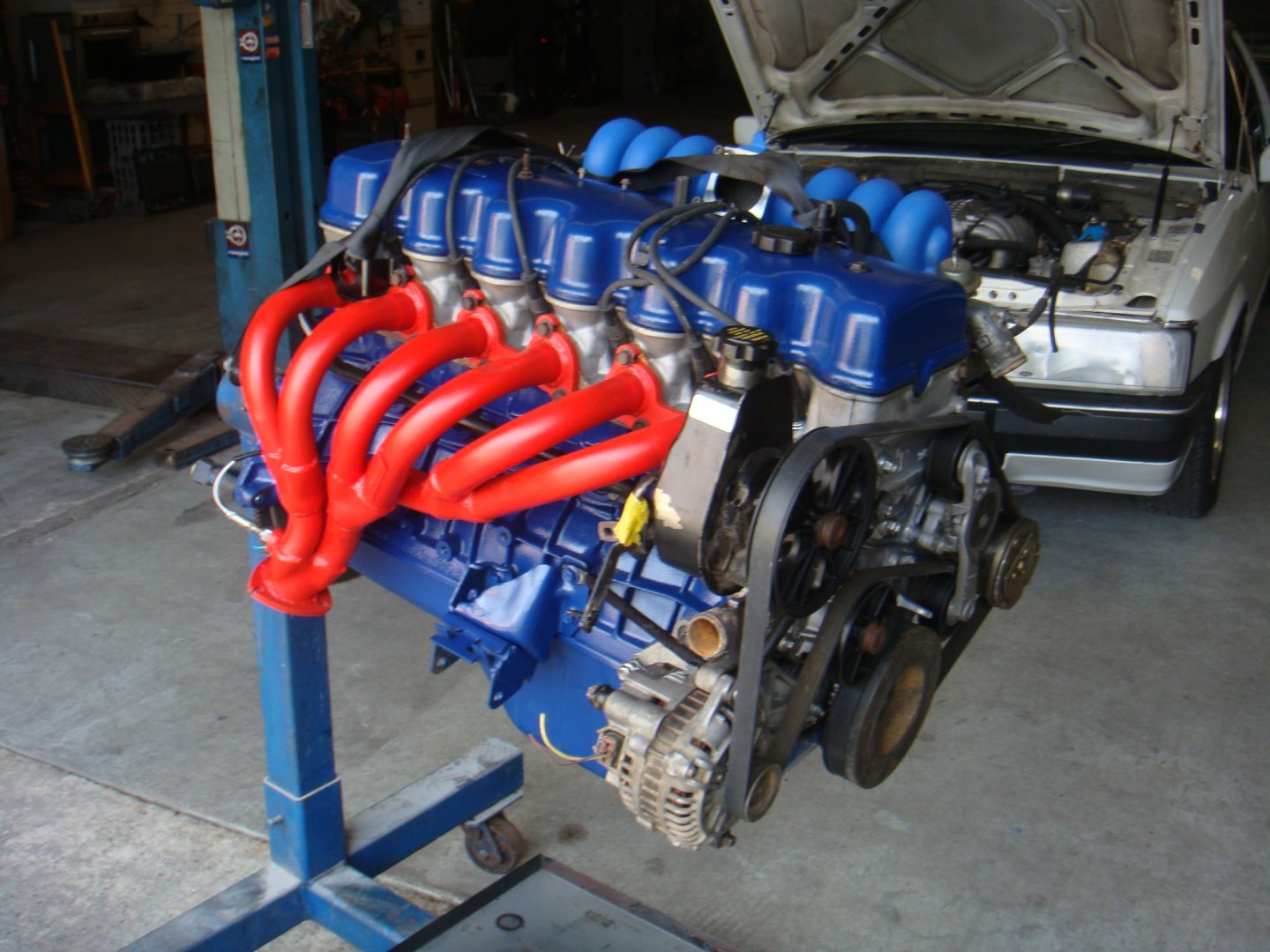
i have a bbm on my sohc 4 litre , but have no clearance between manifold and dissy,, its so close i can't get leads on and its out of the car .... is there different height dissy caps ,, because the ones I have seen at the wreckers all have a little bit of room .even enough to get the cap off if need be ... i have triple checked to see if my dissy was in properly as well ..motor is ef and used to have coil packs , but have changed to dissy..... it's so anoying i am thinking of going back to a log manifold , but then I will have to make up cruise control cable
-
well i have just ordered the plug and play microsquirt from efi source $475usd + post, https://www.efisource.com/wp/shop/microsquirt-for-1986-93-ford-5-0-mustang/ just over $850aud for a fully programable computer i have used them before on a 2.7 litre kombi and a ls1 turbo , and they work great for the money . they are an entry level system ,but still have a lot for the money .... the one i got is for the 86 fox body mustang , same 60 pin plug as our falcons , and 98% the same pinouts as our falcon , the changes for it to work are...[from efi source ]..............
here are the minimum changes that I can see that would be required:
- Make sure the unused pins 12-15 and 42 are indeed not populated with wires (these are all additional injector channels on the Mustangs)
- As this is an off-road use only ECU, it will not control any emissions equipment like the EGR/vent/purge solenoids. Most of these pins are disconnected it the ECU, however there are a few used for other intended functions that might give you conflicts:
- Pin 31 is a PWM output intended for a boost controller output
- Pin 52 is meant for another injector output
- Pin 43 is meant for one of the factory narrow band O2 sensor inputs...........All of the other important things seem to be the same though - ignition, crank signal, idle valve, sensors, grounds, etc. .............. to run the btr i will be using a shift kits manual control for now ,,, then I will get another microsquirt to control the btr latter on ...... the easy thing with this setup is i can use canbus between both computers........ this will all go in when i turbo charge it early next year . i will run it naturally aspirated first .
gerg reacted to this -
9 minutes ago, deankdx said:i couldn't tell you if it's different to ED, but i'd be surprised if it was.
@Thom could probably confirm it easily, he's our 4.0 expert I believe
i wouldn't have thought they would be different as well , but after looking at how the leads are hard up against the bottom of the manifold ,there just might be 2 different heights in dissy caps. i might go to repco tomorrow and ask
deankxf reacted to this -
On 7/20/2022 at 11:04 AM, damo9999 said:i made a mistake on the wiring colours for the o2 sensor.. i found this
Heater positive - Grey/Yellow stripe
Heater negative - Black/Dark Green stripe
Sensor signal - Dark Green/Dark Blue stripe........ on pankos thread ,and its the colours i have as well ...... i am still not sure if ground goes to battery ground , or sensor ground .
i just found the answer to my o2 ground question . pin 49 on the computer is a dedicated 02 ground
-
3 hours ago, deankdx said:the EL falcon had the BBM and a dissy.
if you need to remove the dash, it can be removed 90% complete, it was under heater core replacement in the Gregory's manual.
there's a write up on here but i can't find it right now.
basically what you need to remove is the radio (due to the antenna lead plugging into the back) and any aftermarket wiring that's been connected (alarm, speaker wires etc)
and before doing much else unscrewing the cable off the heater box behind the glovebox for the blend door(screen/feet etc lever) and unplug the fan wires from dash to heater box soon as you can access them.
I've seen Dash's pulled down to near nothing while still in the car and it's not necessary
you may be able to just swing it out a little, by undoing the 2 bolts behind the front of the console, and the 2 bolts that go into the A pillars roughly near the door light switches but there's 5 screws under the winsdcreen vents so you can't go too far out due to it being curved or it will break the mounts(perhaps removing the 3 screws on the left side of the screen area would be enough
i know that the el had the bbm and dissy , did they use a different dissy cap than the ed ,because if you have to change leads with the bbm, you will have to take the manifold completely off.... with the dash if it has to come out , i was going to try and just try and just move the passenger side out just a bit ,enough to get the wires behind it
deankxf reacted to this -
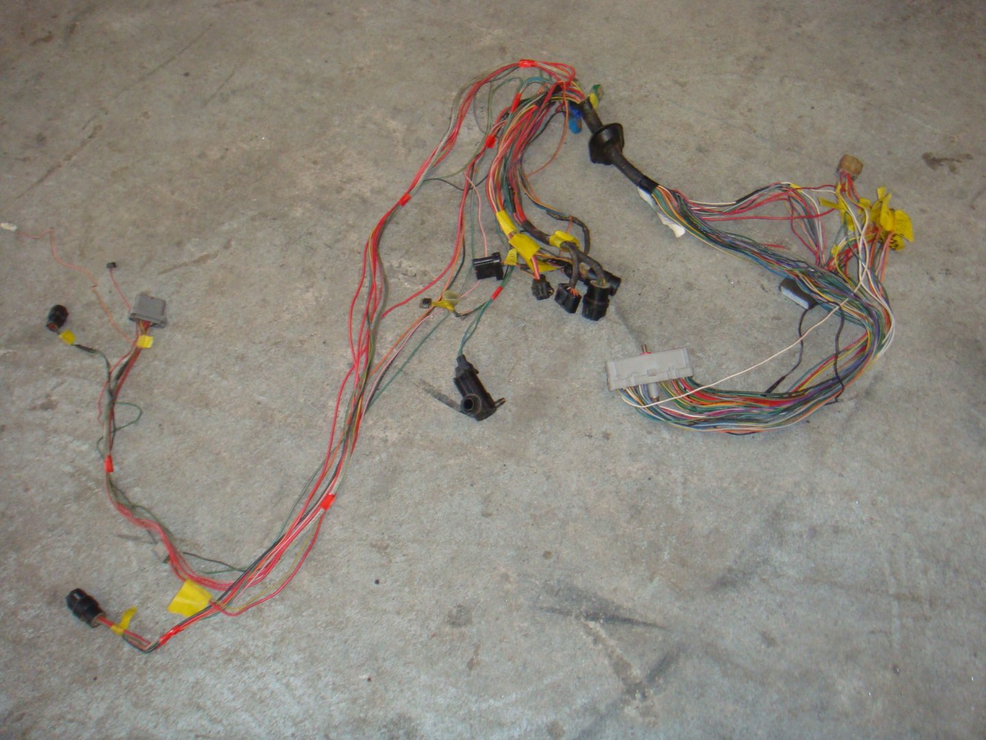
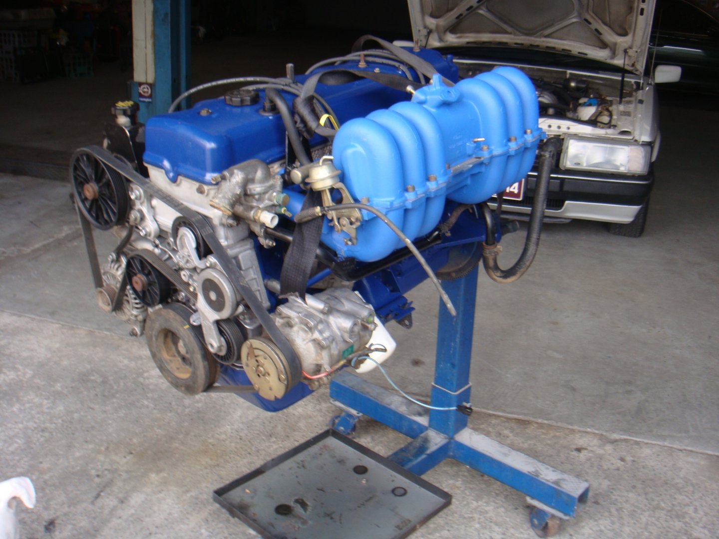
i have started to go through the wiring loom and taken out anything i didn't need ..i have also labelled every wire on my pinout chart .. i am going to replace the engine loom only ,, so hopefully I don't have to pull out the whole dash ,and can get away with only pulling out the glovebox , but I don't like my chances............ the engine is a el xr6 , with extractors , i am thinking about going to a log manifold ...as there is no room under a bbm manifold for a dissy (or only just ) ..the log has a bit more room under it
-
-
i made a mistake on the wiring colours for the o2 sensor.. i found this
Heater positive - Grey/Yellow stripe
Heater negative - Black/Dark Green stripe
Sensor signal - Dark Green/Dark Blue stripe........ on pankos thread ,and its the colours i have as well ...... i am still not sure if ground goes to battery ground , or sensor ground .
-
does anyone know the wiring of the o2 sensor in an el falcon . 1 wire goes to pin 29 on the computer ..wiring colours are 2 x white wire 1 x black wire ,,,, then on the el wiring side (on the other side of the plug ) its black /yellow stripe , green / black stripe , straight green wire ...... witch one goes to pin 29 , then does earth go to sensor ground or battery ground , and third wire must be posative................ thanks ................... i can't find any wiring diagrams anywhere
-
15 hours ago, deankdx said:also a good opportunity to check/replace the 30yr old heater core also and the sealing foam where the heater box meets the dash etc
i dont think the xg dash loom would work ,my xf ute was built by a local automotive tafe ,so they used a complete ltd to use as a donor car for all its ltd only parts including complete wiring loom and dash ...so it has trip computer ,cruise control ,star wars dash , also has complete ltd front ,it even had a brand new efi motor (not rebuilt ) donated by ford with no engine number ever stamped on it . it was a pain to get registered as I had to get a letter from the tafe
-
i am looking at just using my existing efi wiring and adding the extra wires in. i will be using the el computer ,as i want to run the bbm manifold .i won't be using a j3 chip ,i will use one of the smart lock boxes from ebay, as the motor is a stock el xr6 motor .then all i have to do is wire up the btr witch is 9 or 10 extra wires
-
i have read somewhere that the ea2 engine / gearbox loom (and only ea2 as its the first of the 4 speeds and non smart lock) is a stand alone loom and then all you connect is the white 8 pin plug under the brake booster .... but i cant find any wiring diagrams or any other info on this method ,all wiring diagrams i have found start at eb2 on , nothing earlier, i have read panko;s thread ,and do like the way he has done the el computer to crossflow , but the same wiring will work with a 4litre ,then its the extra wires for the btr..............i have spoken to bill hooton about the barra computor and loom but he doesnt really like doing them and he is pretty much booked out for the next 6 months
deankxf reacted to this -
i would never go carby and by the time you buy maifold /carby you can buy 3 microsquirts,,, and i am running a btr .. wiring isnt a problem ,i have wired my 2 other cars with megasquirt and microsquirt computers...just trying to find out the best way of going about the standard ford el computer
deankxf reacted to this -
i was looking at repining the original wiring loom .as its very similar to the el
-
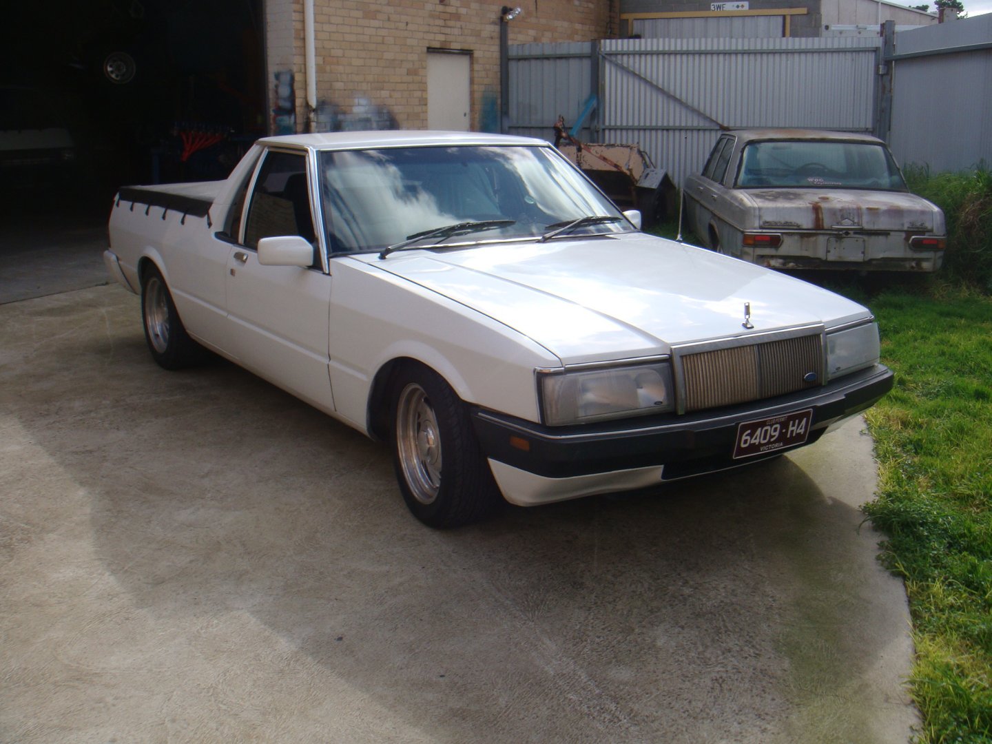
i am doing the sohc into xf conversion , i know its been done heaps of times . but there's so much conflicting info on it . i want to still run the efi with the least amount of wiring... my car is efi already , is the ea2 passenger side wiring loom the easiest with btr loom, or use el passenger side loom , or modify the xg loom, for engine and btr functions only as the xg loom circles the engine bay. i have an xg witch i thought would have been perfect until i had a good look at the computer loom and realised that it circles the engine bay and dash. all i want to do is run the el computer with btr and then join the engine loom to the 8 pin plug under the brake booster ....i don't want to have to pull the whole dash out to fit the xg wiring . just need to know if I am on the right track or am i over thinking it ...hope this makes sense

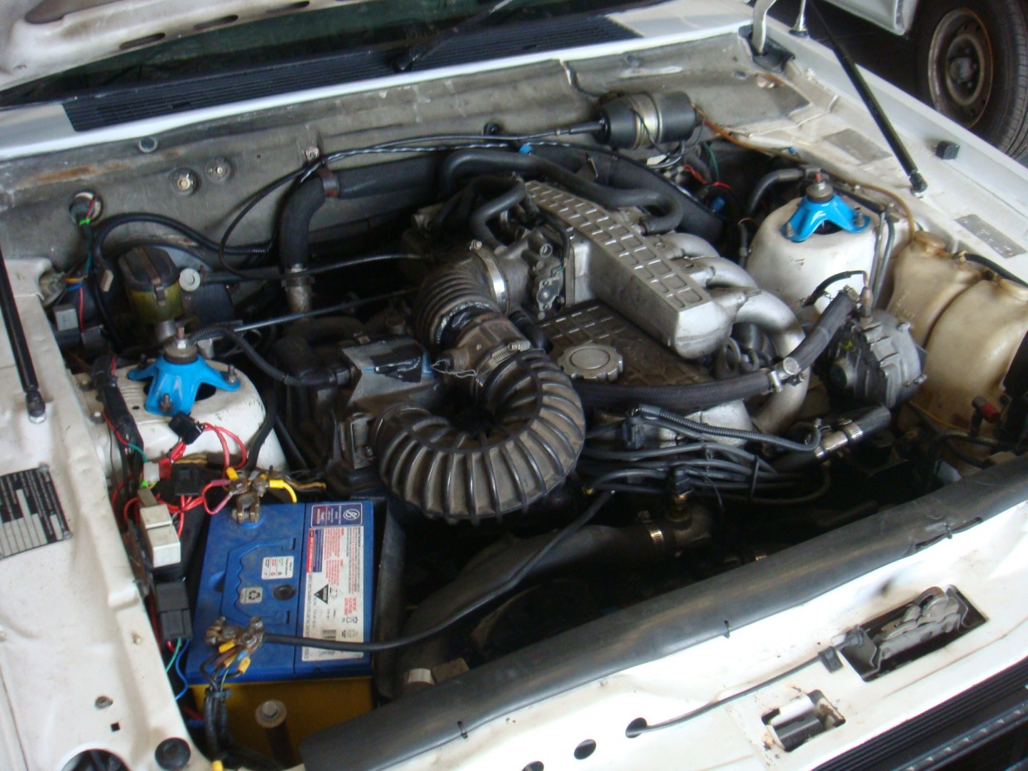
distributor clearance on a bbm manifold
in 4.0 OHC
Posted
i worked out my problem with the dissy..... i have 5 sohc 4 litre dissys and 1 250 crossflow dissy... i managed to put the crossflow dissy in,, which even though it sits on the block and even meshes with the gears just , it sits higher